
Recovery in The Field - 1944

Page 4
Job 1
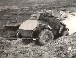
Our first recovery pictures are depicted in Figs 17 and 18, and show an armoured car being recovered from a bog by a 3ton 6 wheel breakdown lorry, fitted with skid pans, and using a 2 to 1 reduction ratio and extended ropes to keep the breakdown vehicle on firm ground out of trouble.
- As the weight of the casualty is 4½ton and the mud and bog index figure is 2, the rolling resistance is 2.2ton (approx).
- The gradient has an average of about 30° and from the previous formulae the resistance works out at another 2.2 tons,
- Total resistance is then(2.2ton + 2.2ton)
- Adding 25% of this for safety and frictional losses we arrive at a winch load of 5½ton and as the maximum on this vehicle is 5ton, the simple 2 to 1 reduction ratio is used to avoid the risk of mishap.
Job 2
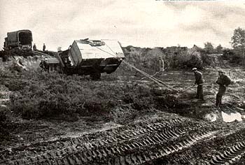
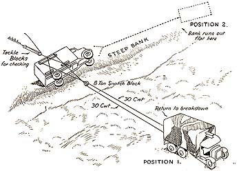
Our next illustration Fig19 is another example of the use of a 3ton breakdown lorry for recovering a 6ton machinery lorry lying on its side over a steep bank.
- To right an overturned vehicle on to its wheels or tracks involves a turning resistance and for calculation purposes the maximum pull required is assumed to be half the weight of the vehicle.
- With the breakdown lorry on firm ground with skid pans in position and using a 2 to 1 reduction ratio we have the layout as graphically portrayed at position 1 in the drawing Fig20.
- From both photograph and drawing it will be seen that tackle blocks are used to obtain a 4 to 1 reduction ratio for checking the downward movement of the lorry on to its wheels once it has passed its vertical pivoting point.
- After righting, the lorry is recovered by a direct pull from position 2 as indicated in the drawing.
Job 3
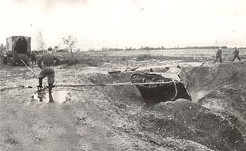
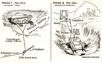
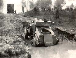
The third recovery example again employs a 3 ton 6 wheeled breakdown lorry as indicated in Fig21, this time for recovering a 5½ton light tank on its side in a bogged crater.
- Here, a right angled pull of 2ton through an 8 ton snatch block secured by two holdfasts is arranged for phase 1,
- to right the tank, Fig22,whilst 4 to 1 reduction tackle is used for checking by the two men seen to the right of the photograph.
For recovery to roadway, a direct pull through a 2 to 1 reduction ratio is employed as indicated in Phase2 of drawing, the winch rope, after passing through the 15ton snatch block, being secured to the ground by two holdfasts. It will be noticed that, as the winch rope passes over the edge of the crater, a wooden roller prevents the wire rope dragging through the earth.