
Recovery in The Field - 1944

Page 3
Technical Problems
And now for some of the technical problems.- involved in the recovery of casualties of various kinds and how they are solved by R.E.M.E. personnel.
First of all, a few remarks about the standard recovery equipment will help readers to understand the methods employed as illustrated in the next series of photographs.
Recovery vehicles are all equipped with ropes, rope slings and tow ropes of composite chain and wire rope, whilst all winches are fitted with wire ropes, it is therefore essential that recovery personnel should be able to calculate the safe working loads for this equipment.
Holdfasts
-which are devices for anchoring vehicles or pulley blocks, are divided into four classes-:
- Natural anchorage's such as trees and rocks, etc..
- Local features such as buildings, concrete defence works, etc.., anchoring as near to the foundation as possible.
- Vehicles using their brakes and skid pans to give good anchorage.
- Recovery holdfasts or ground anchors.
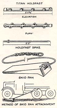
When anchorages under (1), (2) or (3) are not available, or not sufficiently strong for the operation, then ground anchors have to be constructed using the standard equipment of Titan holdfast and spikes (see Fig. 14).
With reasonably hard ground, each of the 3 ft. long spikes will take a load of ½ton, therefore one holdfast with all eight spikes in use will take a load of 4ton. For greater loads on the anchorage, further holdfasts must be laid, preferably in a straight line.
Snatch Blocks
-of the usual single sheave type, have one side cheek hinged to allow the rope to be inserted.
They are made in three types having safe working loads of 8, 12 and 15 tons respectively and are chiefly used
- to obtain an indirect pull, and
- to obtain a reduction ratio using a winch gear.
Skid Pans
- form part of the equipment and consist of steel pressings which are connected by means of a hook and steel wire rope to the chassis of the breakdown vehicle, in near vicinity to the winch mounting. They are fitted under the wheels and anchor the vehicle for winching purposes as indicated in Fig. 15; they also remove the strain of the winch from the chassis and suspension.
Other equipment includes
- Trewhella winch, a portable 2-speed hand operated winch anchored to a holdfast, which, with two men, will exert a direct pull of 12ton
- rope grabs,
- tackle blocks,
- shackles and links,
- towing bars and frames, and,
- overall tracks, the latter being in the form of a steel track to fit over the two pairs of rear wheels of a six-wheeled breakdown vehicle.
The Main Technical Problem in Recovery
is to move a casualty of which the total resistance to moving can exceed 50 tons. The only force available to move this casualty is the pull which can be exerted by the vehicle's winch, which ranges from 4 to 12 tons according to the breakdown in use. The method of solving this problem is to lay out the equipment to give a mechanical advantage over the winch pull, and this is accomplished by laying out velocity ratios.
For calculating purposes the velocity ratio is the ratio between the length of rope wound on to the winch drum and the distance moved by the casualty, whilst the mechanical advantage is the velocity ratio less frictional losses, which in actual practice amount to roughly 10% of the applied load to each sheave.
The rolling resistance is the pull required to move a vehicle on level ground and is a function of the ground resistance, wheel diameter, width of tyre or track, etc., and all these conditions have to be borne in mind. In calculating this resistance it is interesting to note that the weight of the casualty is divided by the index figures indicated for the following conditions:-
| smooth road | 25 |
| grass | 7 |
| gravel | 5 |
| soft sand | 4 |
| shallow mud | 3 |
| heavy mud and bog | 2 |
The grade resistance due to gravity when moving a vehicle up a slope also comes into the calculations and a rough figure is obtained by taking the resistance as 1/60th the weight of the casualty for each degree in angle of slope up to 45°, over which the complete weight of the vehicle is considered.
From the foregoing, let us consider the velocity ratio required to recover a 20 ton casualty up a gravel slope of 15deg using a 3 ton 6-wheeled breakdown vehicle.
| Rolling Resistance(Rr) | = (weight of veh)/(gravel index) = (20ton)/(5) |
= 4ton |
| Gradient Resistance(Rg) | = (weight)x(angle)/(60) = (20ton)x(15°)/(60) |
= 5ton |
| Total resistance(Rt) | = (Rr)+(Rg) | = 9ton |
| Safety and frictional loss(Fs) | = (Rt)/4 = 9ton/4 |
= 2ton |
| Total load by winch | = 11ton | |
As the maximum winch pull on this type of breakdown vehicle is 5 tons, a 3 to 1 simple reduction layout is required.
Simple reduction layouts are used in ratios of 2, 3, 4, 5 and 6 to 1, above this frictional losses are very great and a large amount of equipment is required.
Compound layouts of 4, 6 and 8 to 1 have a low frictional loss, a smaller number of snatch blocks is necessary- an 8 to 1 compound requires 4 blocks as against 7 for an 8 to 1 simple .... and a shorter length of winch rope is used. Special attention has to be given however to the distribution of loads on the snatch blocks and other equipment and an additional length of steel cable must be available.
Our engineering readers will have realised from the somewhat detailed information we have given that the art of recovery is indeed a science, and that to be successful requires a quick brain trained in rapid and accurate calculations, for the value of the operation depends on prompt action in retrieving casualties, often from under the nose of the enemy, without incurring further damage and without loss of personnel.
Recovery with Anchorage Tackle.
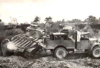
And now let us see how this is carried out in the field. As a preliminary to the recovery of a tank casualty for example, it is essential that means are available of securing the towing equipment to properly designed towing points and in Fig. 16 we see that a 2nd echelon machinery lorry of the type `K light' (electric welding and blacksmiths) has arrived to enable a towing eye-broken off in action-to be welded to a Matilda tank to facilitate recovery.
The lorry is fitted with an engine driven electric arc welding plant and a 26" by 20" portable blacksmith's forge for hand or electric fan operation from the 110v. DC. generator installed. This type of job has often to be done at night and then the operator has to work under a large tarpaulin spread over both lorry and casualty.