
Adjusting Centurion Tracks

WO1 Robert Thompson
Artificer Armament
Artificer Armament
I have answered almost a dozen requests on the "how and when" of Centurion Track adjustment. This from the manual but I will of course give any further advice needed through the RAEME.Net
- Preliminary Notes
- A correctly adjusted track has a 25mm sag between the 2nd and 3rd top rollers
- Number of links should be no more than 108, no less than 103.
- Preferably Tank to be on flat and hard standing.
- Tools
- Spanner Adjustment Nut locking screw.
- Spanner Adjusting Tension Nut for Idler Wheel.
- Drift. Commonly called secondary pins with handle.
- Cold Chisel
- 680gram hammer.
- Tool assembling circlip.
- 6kg Sledge Hammer
- 1.5m Crowbar.
- Slacken Track Tension
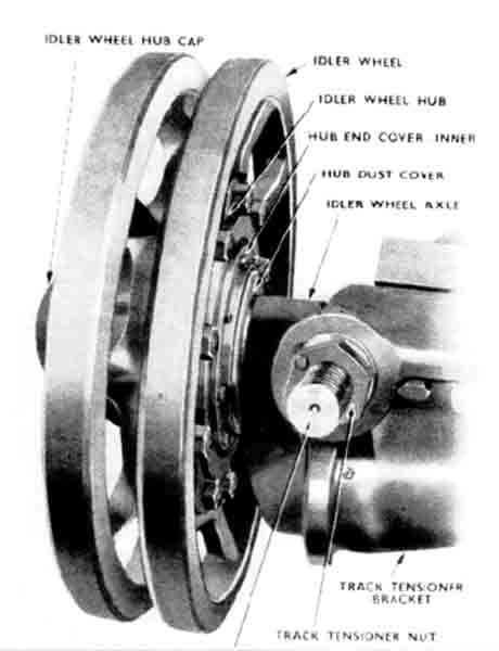
- Slacken the pinch bolt on the adjusting nut of the idler wheel.
- Unscrew the Idler Nut anti-clockwise six turns only, if more required make sure nut stays with at least 4 threads within the nut.
- Reverse the vehicle very slowly, this will allow the Idler Wheel to move back.
- Using neutral turn steering gather all the slack under the Final Drive Sprocket, disengage the clutch and at the same time apply the handbrake.
- Remove Track Link.
- Select two track pins approximately half way between the sprocket and the road wheel.
- Strike the head of both track pins (nearest the hull) so that the circlip is clear of the spacing washers.
- With hammer and cold chisel cut through the spacing washer using the gap in the circlip to obtain the required depth of cut.
- Using secondary pin with wire handle start to drive out both track pins.
- Support the track with your crowbar drive the track pin all the way out. Do the same with the second track pin.
- Rejoin Track.
- Place the crowbar under the bottom track.
- Put your secondary pin partly into the bottom track pin hole and offer it up to the adjoining track. When they marry up push the secondary pin all the way through.
- Insert the track pin from the outside (nearest the hull) driving it home and at the same time driving the secondary pin out.
- Fit a spacer washer over the end of the pin, ensuring that the recess is to the outside, so that it will retain the new circlip when positioned.
- Fit a circlip to the circlip assemble tool and place the tool into position over the end of the track pin, at the same time, (two people) hold your sledge hammer to the head of the pin then strike the circlip holder tool with a hammer, locating the circlip into position.
- Adjust Track Tension.
- Release handbrake.
- Take up slack below the Final Drive Sprocket using your neutral turn steering lever and again apply the handbrake.
- Tighten the track, using the Spanner Adjusting Tension Nut (and it’s extension) by turning the adjuster nut in a clockwise direction until there is 25mm (1inch) sag between the 2nd and 3rd top rollers — A straight-edge or a length of cordage held taunt along the track will indicate the sag.
- Tighten the pinch bolt on the adjusting nut.